
Last month I shared a step-by-step teardown guide for the Surface Pro 3 docking station. This time I’ll dive a little deeper into the 40-pin “surflink” aka SurfaceConnect connector. I only did this to see what was inside and ended up destroying the connector so I don’t recommend repeating the process. Unlike the 12-pin connector on the factory power supply, there are no magnets or solid ferrous metal bits here. So the connector may need a little help staying seated in the SP3 tablet when not embedded in a docking station. I didn’t have my regular camera with me – just my Nokia 635 Windows Phone. I think the pictures turned out pretty well for a $50 no-contract phone though.

Tools:
- Dremel or similar rotary tool
- Pliers
- end-cutters
- putty knife or razor blade
- Clamp to hold connector while working the Dremel (optional)
Disassembly
- Use the Dremel tool to slice along the injection moulding seam. Slice carefully and only cut through the black plastic. As you cut, you’ll see the copper foil shield underneath. Don’t cut into the shield yet:

![7651.WP_20150609_17_55_37_Pro[1]](https://dancharblog.files.wordpress.com/2015/06/7651.wp_20150609_17_55_37_pro1.jpg?w=1000)
- With pliers and end-cutters, remove the black plastic:

![1602.WP_20150609_18_11_34_Pro[1]](https://dancharblog.files.wordpress.com/2015/06/1602.wp_20150609_18_11_34_pro1.jpg?w=1000)
- With a putty knife or a razor blade, peel away the copper foil shield:

![6433.WP_20150609_18_14_04_Pro[1]](https://dancharblog.files.wordpress.com/2015/06/6433.wp_20150609_18_14_04_pro1.jpg?w=1000)
- Keep going, this will take a while since what is underneath is quite sticky:

![7418.WP_20150609_18_18_06_Pro[1]](https://dancharblog.files.wordpress.com/2015/06/7418.wp_20150609_18_18_06_pro1.jpg?w=1000)
- Finish by cutting the copper foil away from the braided shield on the USB, DisplayPort, and power cables:

![7532.WP_20150609_19_19_27_Pro[1]](https://dancharblog.files.wordpress.com/2015/06/7532.wp_20150609_19_19_27_pro1.jpg?w=1000)
- Cut and peel away the clear stuff. I don’t know what it is made out of, but I think it is there to secure all the wires and provide strain relief during assembly. It is squishy, sticky and very difficult to get off. If you try to pull it all off, you’ll probably break a few of the solder connectors on the tiny wires like I did:

![8688.WP_20150609_19_45_39_Pro[1]](https://dancharblog.files.wordpress.com/2015/06/8688.wp_20150609_19_45_39_pro1.jpg?w=1000)
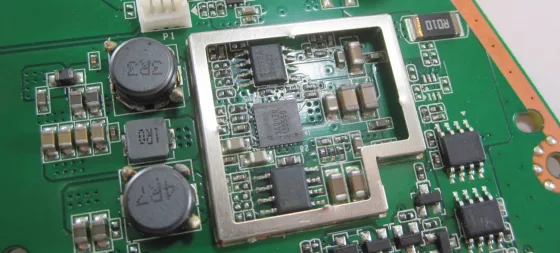
- After peeling away all the sticky stuff you can see all the components on the tiny PCB:

![3365.WP_20150609_19_45_51_Pro[1]](https://dancharblog.files.wordpress.com/2015/06/3365.wp_20150609_19_45_51_pro1.jpg?w=1000)
Observations
- PCB appears to be 4-layer and has lots of vias
- The proprietary 40-pin “surflink” connector mounts over the edge of the PCB and is reflowed on both sides – similar to how some mini-DisplayPort connectors are attached
- 3 discrete transistors
- 4 resistors
- 1 diode
- 4 8-pin integrated circuits marked “4CH”. It appears that each IC has 8 pins – 4 in 4 out and a ground connection under the chip with a solder blob. I suspected these were some sort of ESD protection device for the various data channels, but it turned out there are driver chips for the highspeed differential pair lines (DP_ML and USB_SS)
- The charging indicator LED (grey wires) appear to be connected to the discrete transistors/resistors through the “HPD2” pins from the 40-pin connector.
- With a multi-meter I determined the pinout of 3-pin connector coming off the miniDisplayPort:
- Pin 1 – CONFIG1/CONFIG2 pins on DisplayPort and to ground through a 1Mohm resistor
- Pin 2 – ground/DP_PWR_Return
- Pin 3 – +3.3v @500mA DP_PWR
- More reverse-engineering info the 40-pin connector pinout provided by Mikhael in the comments:
Pin Signal Destination             Pin Signal Destination
1 +PWR                             2 +PWR
3 HPD1B (Sense?)                   4 HPD2 ???
5 GND                              6 GND
7 DP ML_Lane0(p) MiniDP /3         8 USB D- USB/2
9 DP ML_Lane0(n) MiniDP /5        10 USB D+ USB/3
11 GND                            12 GND
13 DP ML_Lane1(p) MiniDP /9       14 NC
15 DP ML_Lane1(n) MiniDP /11      16 DP Hot Plug Det MiniDP /2
17 GND                            18 GND
19 DP ML_Lane2(p) MiniDP /15      20 DP ML_Lane3(n) MiniDP /12
21 DP ML_Lane2(n) MiniDP /17      22 DP ML_Lane3(p) MiniDP /10
23 GND                            24 GND
25 DP Config 1 MiniDP /4          26 USB Stda_SSRX- USB/5
27 NC                             28 USB Stda_SSRX+ USB/6
29 GND                            30 GND
31 DP AUX_CH(p) MiniDP /16        32 USB Stda_SSTX- USB/8
33 DP AUX_CH(n) MiniDP /18        34 USB Stda_SSTX+ USB/9
35 GND                            36 GND
37 HPD2 ???                       38 HPD1A (Sense?)
39 +PWR                           40 +PWR
Back to the main blog: https://dancharblog.wordpress.com

aloha dan!
i'm glad you did this one as well, i was wondering what was in there!
your last post helped me out quite a bit; I've been looking to mod my dock as I am not a fan of the angle it sits at, and just wanted a more portable way to carry around my dock (the odd shape doesn't really fend well in luggage/gear bag). basically I ripped it apart to step 3, got rid of the backing, and put it back together. (here: instagram.com/…/4ApSFAFphr )
for my purpose, I took the magnet from the left side and added it to the black molding behind the connector… i was thinking of adding another small magnet back there as well for good measure (http://www.amazon.com/…/ref=sr_1_14) just to ensure a good solid pull.
anyway, i was just curious: in your professional opinion, do you think the magnet placement and/or adding another magnet would have adverse effects? it seems to be shielded well, it's performing as it should, and i am getting no additional noise (i produce music for a living), but i figure someone who does this on your level would have better insight.
again, thanks for your time. like you i am an avid supporter of the surface pro 3 and have been using it almost since launch a year ago, despite colleagues of mine thinking i'm lying or just being in pure disbelief when i show them haha
cheers! -mike
LikeLike
Glad its working for you Mike and thanks for sharing the pic. Very cool. Just checking out your soundcloud now… I don't think adding the magnets would have any adverse effects so I think you should go for it! But make sure those little magnets are glued on really tight – you don't want kids or pets getting ahold of them.
When you get a chance, can you share a full picture of your desktop with external monitors and audio gear? I'm really curious to see how you're using everything together.
Cheers,
Dan
LikeLike
dan thanks for the reply! sorry i didn't realize you responded to both. will do when I have a chance!
LikeLike
Aloha Dan,
here's a link to my temporary setup with pics of the dock mod (it's not pretty and neatly finished but I will eventually get around to making it all spiffy).
http://www.dropbox.com/…/AABtTbii9cHDR0ct41q8JQlpa
also i just moved so when I get the full setup going ill make sure to keep you updated!
LikeLike
idk if you had anything to do with the new dock for the sp3/4/book, but nonetheless thank you to you and ms team!
LikeLike
Mike, thanks for the comments. No I did not have anything to do with the new dock. But I played with it last week and like it a lot. It ought to work great for your scenario and integrate into other solutions quite well.
LikeLike
Thanks for the tear down. I recently bought a surface pro 3 to replace my surface pro, I already have a Targus dock and would love to just use the 40 pin connector for USB3.0 and power. I have scoured the net looking for an adapter that includes the USB but they only seem to have power. Do you know of any?
LikeLike
@Jess
As far as I know, there are no vendors offering the solution you describe.
What some folks do is get the MS docking station and plug the Targus into it to get additional ports and monitor outputs. I have tried this approach and it works, but its a lot of boxes and cables on your desk. You could always sell the Targus and buy the MS dock…
Just out of curiosity, how much would you be willing to pay for a converter cable that had the 40-pin connector with magnets on one end and a receptacle for 12V power and a USB 3.0 port on the other end?
LikeLike
Thanks for the quick reply.
I was thinking around $40 to save buying another dock for $200. The new MS dock for the surface 4 looks perfect
http://www.microsoftstore.com/…/productID.325725200
If you have no plans for the 40 pin connector you pulled from the dock I am an electronic engineer so I'd happily buy the bits from you and experiment with them. Otherwise it looks like I'll be buying a new dock. Thanks
LikeLike
@Jess, I messed up the connector – you don't want mine even if you have reflow tools etc. You might want to bid on this broken dock and just do your own teardown: http://www.ebay.com/…/252141202319
LikeLike
Hi Danchar,
Do you have any new information regarding the dock connector pinout? I disassembled the dock station to the level of the connector with cables. I found USB pins, but Display port data is not connected directly to pins, I assume, the small board have a drivers/buffers (probably, you assumed that it is ESD protectors). Also I cannot define power (2 pins from each corner).
LikeLike
@Mikhael
The connector spec is proprietary and provided to partners who sign an agreement with Microsoft as part of the Designed for Surface Program. To get the full spec, apply here: http://www.microsoft.com/…/partner-sign-up
That being said some of the pins are certainly easy to reverse engineer – just very tedious. I do remember that by simply following traces on the little board, there was some symmetry involved which led me to believe it was a reversible connector (confirmed with the release of SurfaceBook and the new Surface Pro 4 docking station) So the high-speed lines like USB super speed and DP ML must be grouped together and the DP AUX/HPD/CONFIG and USB 2.0 low-speed lines must be grouped together. That way when you flip the connector, the same wires are always used for high-speed data vs low-speed data (high-speed pairs and low-speed pairs have different specs)
We know DP has 4 pairs of high speed, 1 AUX low speed and some control pins like HPD/CONFIG. USB3 has 2 pairs of high speed and 1 pair of low speed. So we have 6 pairs of high speed total and 3 or 4 pairs of low speed. From trivial inspection we know that every 3rd contact is ground.
So if you run down one side of the connector it should be something like this:
+12v, power hot plug thingy, ground, highspeed data, highspeed data, ground, highspeed data, highspeed data, ground, highspeed data, highspeed data, ground, lowspeed data, lowspeed data, ground, lowspeed data, lowspeed data, ground, power hot plug thingy, +12v
And the other side would be the reverse order so when you flip the connector everything matches up.
The polarity of the differential pairs would have to be consistent for a reversible connector as well. So if you mapped out USB, you already know the polarity of all other differential pairs. You just need to map out which DP ML lanes are which.
I think the DP HPD pin was straight through. DP Config pin I already explained as coming out that little 3-pin connector and grounded through a 1Meg resistor on the dock motherboard. So deducing which lanes are DP AUX is easy.
If you want to figure out how the power hot-plug thingy contacts work, try cracking open a $10 knockoff power brick from ebay.
Hope that helps.
LikeLike
Hi Danchar,
Thank you for your quick and complete reply.
We already signed the NDA with MS. They promised to join us to their customer program, I got contacts and 1st reply, and after this, about 3 months I don't receive any answer on my repeating questions.
Anyway I did reverse engineering and defined following pinout:
Pin Signal Destination             Pin Signal Destination

1 +PWR PWR con/6, 7                2 +PWR PWR con/6, 7

3 HPD1B (Sense?) Pwr con /3        4 HPD2 ???

5 GND                              6 GND

7 DP ML_Lane0(p) MiniDP /3         8 USB D- USB/2

9 DP ML_Lane0(n) MiniDP /5        10 USB D+ USB/3

11 GND                            12 GND

13 DP ML_Lane1(p) MiniDP /9       14 NC

15 DP ML_Lane1(n) MiniDP /11      16 DP Hot Plug Det MiniDP /2

17 GND                            18 GND

19 DP ML_Lane2(p) MiniDP /15      20 DP ML_Lane3(n) MiniDP /12

21 DP ML_Lane2(n) MiniDP /17      22 DP ML_Lane3(p) MiniDP /10

23 GND                            24 GND

25 DP Config 1 MiniDP/4           26 USB Stda_SSRX- USB/5

27 NC                             28 USB Stda_SSRX+ USB/6

29 GND                            30 GND

31 DP AUX_CH(p) MiniDP /16        32 USB Stda_SSTX- USB/8

33 DP AUX_CH (n) MiniDP /18       34 USB Stda_SSTX+ USB/9

35 GND                            36 GND

37 HPD2 ???                       38 HPD1A (Sense?) Pwr con /5

39 +PWR PWR con/6, 7              40 +PWR PWR con/6, 7
DP ML_LaneX(p, n) are routed via differential drivers according application notes
As I assume, HPD1A, B are connected to +PWR via any resistor inside the SPro3. Do you know, are they joined by OR gate or are checked separately? What is a condition to Power ON? (when no SPro, the power is "hicking"). The HPD2, power connector pin 4, I did not found coming to the SPro connector. What is his function?
LikeLiked by 1 person
Wow nice work Mikhael! Thanks for sharing your findings.
Sorry to hear about the lack of response from the program. Not sure what's going on there.
I think pin 4 and 37 in your chart are the "HPD2" function printed on the little circuit board. I had trouble following the connections with all the little vias so I'm not exactly sure what's going on but its likely a feedback mechanism to control power delivery to the tablet.
What is your goal here?
Do you want to 100% reproduce the charging scheme implemented in the MS brand docking station? Or do you want to just get the tablet to charge?
There is a simple way to get the tablet to charge with your own power supply: you can buy a "Surface Pro 3 charge cable" on ebay for ~$5 that will convert from an industry standard barrel connector to the 12-pin surface connector. IIRC all that is inside these knock-off assemblies are a couple FETs, a couple resistors and an LED but I don't remember the layout. Just like Apple Mag-safe and Samsung chargers, there is likely a resistor with a very specific value that indicates the expected peak current to the tablet. So open up one of those cables to find the value. Also see if you can find old posts from "Mikegyver" in google cache or waybackmachine. I think he actually documented some of this at one time but I can't seem to find his posts any more.
Keep in mind that with these types of connectors you always have the risk of hot-plug high-current arcing that will destroy the tiny traces over time. So you really want a robust feedback scheme to mitigate that risk. If you monitor the +12v and HPD lines as you connect the tablet to the MS charger with an ammeter and oscilloscope, you may be able to see a feedback mechanism in action.
LikeLike
Hi Mikhael,
Sounds like a very cool project! Sadly, the connectors are 100% Microsoft proprietary and only licensed partners can pull from the MS supply chain.
Do you have the physical space to just include the MS dock circuit board with your solution? The brand new Surface Pro 4 dock also works on Pro 3 and is quite compact. You can disassemble it to remove the lead weight inside – the circuit board is tiny with much less Z-height than what you'd think by its case. Its power supply is still rather large, but not too bad.
LikeLike
Hi Danchar,
I will integrate the tablet in my device. For this purpose I will develop my own communication board communicating with Spro via docking connector. I even don't need to reproduce the charge control, because the device works from its own power supply that also will power the tablet all the time when is turned ON. Also, since the tablet will be embedded and not detachable, the hot plug is not actual.
BTW, I still did not found the connector similar to docking one. Do you know, is it any off-the-shelf part, or a MS custom designed one?
LikeLike
Hi Danchar,
This is only a relatively small part of my project:)
Unfortunately I cannot use a docking station board as it is, I must design my proprietary one to provide all required functions to communicate between the Spro 3 and my device. MS persons that I got their names for contact for this program, still don't answer me after a lot of my repetitive mails.
LikeLike
Hello folks,
following your research, do you think it’s possible to use the surface connect port to plug a USB-C external GPU device ?
LikeLike
Thierry, unfortunately you won’t be able to use an external GPU with the connector on the SP3/SP4. Sound like you might want to trade up to the Surface Book!
LikeLike
Thanks for these detailed teardowns! Do you have any idea why and/or why the connector is built like this? I could sort of understand going with a design like this if they tried routing PCI-E lanes through the connector but this seems massively overkill for something that is only meant to carry power, USB and DP. This is probably going to sound really stupid but with the appropriate docs from MS and Intel would it be possible to modify the pinout on the connector on the Surface motherboard to route some PCI-E lanes and to fashion some sort of makeshift Thunderbolt dock?
LikeLike
Hi,
I suspect the design is a long-term play for a high-bandwidth zero-insertion-force magnetically-aligned connector that can be used for a variety of purposes. I agree it looks overbuilt for its current application of DP1.2+USB3+Power and I reckon it can meet or exceed the bandwidth capabilities of TB3. (I have not hooked up a test rig to measure insertion losses for the cable ends or generate eye diagrams – this would be a fun exercise though!)
TB3 is not possible on current Surface devices – none of the logic is present on any in-market Surface motherboard. You can’t simply re-route PCI lanes on these motherboards. Perhaps you could re-purpose the internal SSD m.3 connector though.
Given the modular design of the Gen 2 dock with the detachable Lorum Cable assembly and fully programmable Freescale microcontroller and switch arrays, I expect future docks and devices from Microsoft will re-use the same connector but support a variety of protocols which could include TB3. Do keep in mind that MS has effectively implemented external-dGPU (a key benefit of TB3) with the SurfaceBook by piping PCI 3.0 x4 on the 2 smaller proprietary connectors. So we know the connector technology is capable.
IMHO, the USB-type-c connector is huge step backwards compared to the Microsoft connector especially for folks with disabilities. However it it much better than micro-USB and USB type-A.
On Thu, Jan 11, 2018 at 12:13 PM, Dan S. Charlton wrote:
>
LikeLike
Thanks for the insight!
LikeLike
Has anyone made or thought of making a MS surface connector to USB-C female connector?
I’m trying to use my USB-C dock on my Surface laptop.
LikeLike
Has anyone looked into creating a MS dock connector to USB-C adapter?
I have a USB-C dock at home and recently received an older surface device that I’m able to use a surface dock to transmit power/data/video with, but I’d like to stop using the surface dock and switch over to my USB-C dock that the rest of my laptops use.
Essentially looking for an adapter or cable that has USB-C on one end and the MS connector on the other.
LikeLike
Microsoft used to make one for the Pro5/Pro6. The intent was for Enterprises to use any brand USB-C dock with the Surface Pro. It was expensive, bulky, and discontinued when the Pro7 launched.
You can find them on eBay from time to time
LikeLike
Hey Dan, I purchased a couple items from aliexpress. This one which is a 65W surface connector to male usb-c cable, and this one which is a 102W surface connector to female usb-c. I have received both and haven’t tested them yet. I picked up and returned a used Surface 7+ earlier this year, and only recently picked up a Surface pro 9.
Slight sidenote, do you know if the surface dock 2 provides power through the usb-c ports? I was thinking of powering a portable monitor or two, but I don’t think it does.
LikeLike